(!)Due to Microsoft's end of support for Internet Explorer 11 on 15/06/2022, this site does not support the recommended environment.
- Scheduled Maintenance Notice: This site will be unavailable due to scheduled maintenance from 9:00 19/4/2026 to 7:00 (MYT) 20/4/2026. We apologize for the inconvenience.
- [Notice] Japan & China Golden Week holidays will start from 29 April to 6 May 2026. Kindly expect longer response from suppliers and possible delivery delay due to high volume of shipments after holiday. Early order placement is recommended. More details
- [Announcement] MISUMI Malaysia website new user interface. Clearer navigation, easy product search and more. Explore now! May contact us at (60) 3 7890 6399 for any inquiries.
NBK Flexible Shaft Couplings(Max. Rotational Speed Range:1001~2000)
Type
-
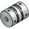 Slit
Slit -
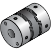 Disc
Disc -
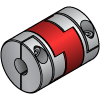 Oldham
 -
 Jaw
Jaw -
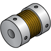 Bellows
 -
 Vibration Damping Rubber Type


-

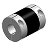
MOM flexible coupling - Oldham type
NBK
[Features]
· Oldham type flexible coupling.
· FCD400 used in spacer.
· Ideal for low speed / high torque specifications.
· Grease applied between hub and spacer to prevent burn-in.
· Due to hub and spacer slip, large eccentricity / deflection angles are allowed.
· The protrusion (resin pin) provided on the spacer allows the angle of deviation without difficulty.
· Long-term maintenance-free.
· Grease accumulated in the grease hole gradually leaks during operation, to maintain long-term lubrication performance.Standard Price: MYR 201.61- Days to Ship: 5 Day(s) or more

| Brand |
|---|
| Product Series |
| CAD |
| Days to Ship |
| Type |
| Allowable Misalignment |
| Application |
| Allowable Torque Range(N•m) |
| Shaft Bore Dia. (machined) D1(Ø) |
| Shaft Bore Dia. (machined) D2(Ø) |
| Outer Dia. A(Ø) |
| Overall Length W(mm) |
| Max. Rotational Speed Range(r/min) |
| Features |
| Body Material |
| Product Category |
| Allowable Torque(N•m) |
| Max. Rotational Speed(r/min) |
| Allowable Lateral Misalignment Range(mm) |
| Allowable Lateral Misalignment(mm) |
| Allowable Angular Misalignment(deg) |
| Buffer Material |
| Disc Material |
| Bellows Material |
| |
| Brand | NBK |
| Product Series | |
| CAD |
|
| Days to Ship | 5 Day(s) or more |
| Type | Oldham |
| Allowable Misalignment | Angular Misalignment / Eccentricity |
| Application | Standard |
| Allowable Torque Range(N•m) | 20.01~50.00 ~ 100 < 500 |
| Shaft Bore Dia. (machined) D1(Ø) | 7 ~ 30 |
| Shaft Bore Dia. (machined) D2(Ø) | 13 ~ 41 |
| Outer Dia. A(Ø) | 26 ~ 70 |
| Overall Length W(mm) | 26.6 ~ 68.6 |
| Max. Rotational Speed Range(r/min) | 1001~2000 |
| Features | High Torque ~ High Torsional Rigidity |
| Body Material | Steel |
| Product Category | Coupling Main Body |
| Allowable Torque(N•m) | 22 ~ 352 |
| Max. Rotational Speed(r/min) | 2000 |
| Allowable Lateral Misalignment Range(mm) | 0.41~1.0 ~ 1.1~3.0 |
| Allowable Lateral Misalignment(mm) | 0.5 ~ 1.4 |
| Allowable Angular Misalignment(deg) | 2 |
| Buffer Material | - |
| Disc Material | - |
| Bellows Material | - |

Loading...
Configure
Specification/Dimensions
-
Allowable Misalignment
-
 Not Provided
 -
 Angular Misalignment
 -
 Eccentricity
 -
 Axial Misalignment
-
-
Application
- Standard
- Servo Motor
- Stepping Motor
- Encoder
-
Allowable Torque Range(N•m)
-
Shaft Bore Dia. (machined) D1(Ø)
-
Shaft Bore Dia. (machined) D2(Ø)
-
Outer Dia. A(Ø)
-
Overall Length W(mm)
- 8.4
- 10
- 11.2
- 12
- 13.5
- 14
- 14.2
- 15
- 16
- 16.5
- 16.6
- 16.7
- 17.5
- 18
- 18.4
- 19
- 19.8
- 20
- 21
- 21.4
- 21.5
- 21.6
- 22
- 22.2
- 23
- 23.1
- 23.2
- 23.5
- 24.1
- 24.4
- 24.5
- 25
- 25.6
- 25.9
- 26
- 26.2
- 26.5
- 26.6
- 27
- 27.2
- 28
- 28.3
- 28.5
- 29
- 29.5
- 30
- 30.2
- 30.4
- 31
- 31.2
- 31.4
- 31.5
- 31.7
- 32
- 32.2
- 32.3
- 32.5
- 32.6
- 32.8
- 33
- 33.3
- 33.5
- 33.8
- 34
- 34.4
- 34.5
- 35
- 35.6
- 36
- 36.1
- 37
- 37.4
- 37.8
- 38.5
- 38.6
- 39
- 39.4
- 39.5
- 39.7
- 40
- 40.5
- 41
- 41.8
- 42
- 42.2
- 43.2
- 43.4
- 44
- 44.2
- 44.7
- 44.8
- 45
- 45.5
- 46
- 46.6
- 47
- 48
- 49.2
- 49.4
- 50
- 50.2
- 50.6
- 50.8
- 51
- 51.2
- 51.3
- 52
- 53
- 53.4
- 54.1
- 54.4
- 54.5
- 55
- 55.5
- 55.9
- 56
- 56.2
- 56.5
- 57
- 58
- 58.5
- 58.6
- 59
- 59.4
- 59.7
- 60
- 60.4
- 60.5
- 61
- 62.9
- 63
- 63.6
- 63.7
- 63.8
- 66
- 66.8
- 67.5
- 67.7
- 68.2
- 68.3
- 68.6
- 68.7
- 68.8
- 69.3
- 69.5
- 71
- 73.3
- 74
- 74.4
- 75.2
- 77
- 78
- 80
- 81
- 82
- 82.5
- 82.7
- 83
- 85
- 86
- 88
- 89.5
- 89.9
- 90
- 90.2
- 90.5
- 91
- 92
- 94
- 94.6
- 96
- 97.2
- 98
- 98.5
- 98.6
- 99
- 99.2
- 99.6
- 100
- 102.5
- 109
- 114
- 126
- 140
- 165
-
Max. Rotational Speed Range(r/min)
-
Features
-
Body Material
- Stainless Steel
- Steel
- Aluminum
- Alloy
- Plastic
- Aluminum Alloy
-
Product Category
-
Allowable Torque(N•m)
-
Max. Rotational Speed(r/min)
-
Allowable Lateral Misalignment Range(mm)
-
Allowable Lateral Misalignment(mm)
-
Allowable Angular Misalignment(deg)
-
Buffer Material
-
Disc Material
-
Bellows Material


Narrow search by specifying Manufacturer
-
- MISUMI_Test (0)
- NBK (1)
- ISEL (0)
- ORIENTAL MOTOR (0)
- NIHON MINIATURE (0)
- SUNGIL (0)
- MIKI PULLEY (0)
- MIGHTY (0)
- ADVANCED (0)
- SAKAI MANUFACTURING (0)
CAD
-
- 2D
- 3D
Days to Ship
-
- All
- 1 Day(s) or Less
- 2 Day(s) or Less
- 3 Day(s) or Less
- 4 Day(s) or Less
- 5 Day(s) or Less
- 6 Day(s) or Less
- 7 Day(s) or Less
- 8 Day(s) or Less
- 9 Day(s) or Less
- 12 Day(s) or Less
Related Categories to Flexible Shaft Couplings
- Credit Card
- Bank Transfer
Social Media
MISUMI Contact
Copyright © MISUMI Corporation All Rights Reserved.
How can we improve?
How can we improve?
While we are not able to respond directly to comments submitted in this form, the information will be reviewed for future improvement.
Customer Privacy Policy
Thank you for your cooperation.
While we are not able to respond directly to comments submitted in this form, the information will be reviewed for future improvement.
Please use the inquiry form.
Customer Privacy Policy